Producing accurate simulations of LED based optical systems requires accurate source models. There are several ways that sources can be modeled and these various methods are discussed in some detail in this technical paper.
Some modeling methods have trade-offs in accuracy and can therefore only be used in designs where the decreased accuracy is acceptable. For most secondary LED optics however, there is little tolerance for compromises in source model accuracy. This is why Photopia's LED source library uses the most accurate type of model possible. These are referred to as Type 3 source models, using the terminology in the paper referenced above.
Type 3 source models are essentially the same as luminaire models that contain lamp, reflective, transmissive and/or refractive surfaces. The proper distribution of light is created only after all of these components interact with each other. Type 3 models are required when the interaction of the components is crucial to replicating the physical lamp's behavior in your optical system and in cases where the Type 1 and 2 models lack the required accuracy in some aspect of the behavior. To illustrate how a Type 3 model works, we'll review a LED example using the Seoul Semiconductor P4 source model.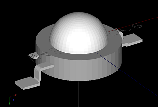
In the LED, light is initially emanated from the side or flat surfaces of the LED chip embedded inside a bulb. Reflective surfaces are also embedded within the bulb underneath. The final distribution of light emitted from the LED package is a function of the following:
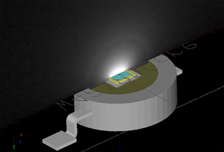
Since Type 2 lamp models in Photopia do not support refraction and reflection of light upon initial emanation, a Type 3 LED model is needed. The reason why Type 2 models don't support refraction and reflection of light within the source model is because the effects of any refraction and reflection are already taken into account in the measured distribution assigned to the model. The main purpose of taking these interactions into account in a Type 3 model is to generate more accurate ray emanation points. See the image below for an example of how the internal structure was modeled for the P4.
The Refractor Module in Photopia is capable of handling the various requirements of LED lamp models. This includes having light start within the bulb material (not air) and having a reflector within the bulb.
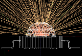
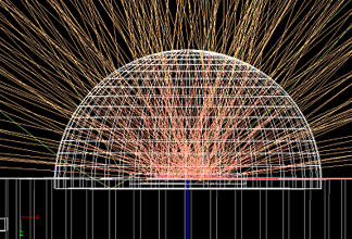
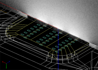
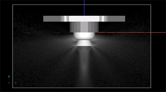
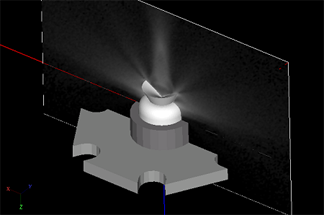
The images above illustrate how the proper angular and spatial distribution of the rays is achieved. Rays emanate from the LED chip and some reflect off of the reflective surfaces while most go toward the bulb/air interface directly. Some light then exits the bulb and is refracted appropriately and some light reflects back into the bulb due to Fresnel's reflections. Depending on the relative size of the chip and shape of the bulb, some light will also get redirected back into the LED via TIR. This is more common in some of the new multi-chip designs as well as the smaller bulbs used in products like the Lumileds Rebel.
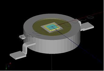
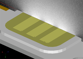
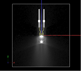
The image above shows the light emitted from the chip on a shaded plot with the bulb layer turned off. The bulb was on during the raytrace and turned off only for this image. You can see how the light initially emits only from the luminous chip.
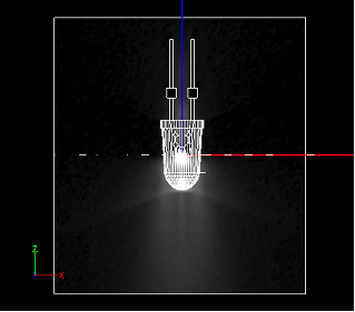
The following images show the pattern of light predicted by Photopia on illuminance planes passing through the center of several different types of LEDs. The images illustrate the near-field light pattern that these models produce, which are only possible when the light interacts with the all of the optical components (reflectors and lenses).
These images show the CL-L220 LED from Citizen Electronics. This uses a multi-chip array embedded within a gel that has been infused with phosphors. The phosphor infused gel is then surrounded by a clear gel. This model shows light emitted from the top and side surfaces of the gel, where the side emitted light is a result of rays that have TIR'd inside the clear gel section as it acts as a light pipe.
These images show a standard 5mm bulb type from Nichia. You can see that light not only emits out the front of the LED but also out the sides and the back. This is all due to the complex interaction of the rays with the bulb geometry.
This relatively complex bulb geometry is for the Lumileds Luxeon Side Emitting LED. This lens is intended to redirect light to the sides by a TIR reflector directly over the chip. Some of the light scatters in other directions however, since the size of the chip results in a wider range of incidence angles onto the TIR reflector than is ideal.
These LEDs illustrate the importance of modeling the real LED geometry in the source model so that it creates the proper near-field light distribution. This is true even for Lambertian LEDs that use hemispherical shaped bulbs. Although these bulbs do not radically change the direction of the rays, they serve to scale the apparent size of the chip which affects the spread of the light from the secondary optics.
Aside from LEDs that include integrated optical components, other Type 3 models in Photopia's library include reflector lamps such as MR-16's and fluorescent lamps such as U-tubes or circular shapes where the lamp to lamp interactions can be interrupted by reflectors inserted between the tubes.